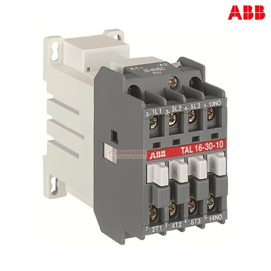
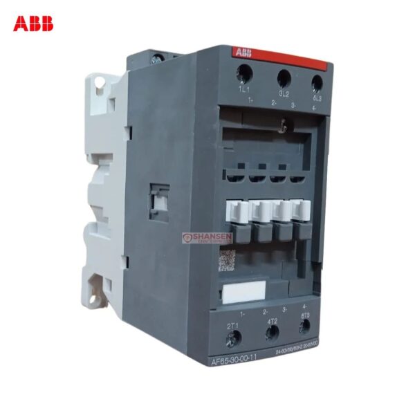
TAL 9 contactors are mainly used for controlling 3-phase motors and generally for controlling power circuits up to 690 V AC or 220 V DC. The contactors can also be used for many other applications such as isolation, capacitor switching, lighting. The TAL... series 1-stack 3-pole contactors are of the block type design. - Main poles and auxiliary contact blocks: 3 main poles, 1 built-in auxiliary contact, front and side-mounted add-on auxiliary contact blocks - Control circuit: DC operated with solid core magnet circuit. The polarity on the coil terminals (A1+ and A2-) must be respected - Accessories: a wide range of accessories is available. TAL... contactors are fitted with low consumption DC coils and offer a large coil voltage range.
Get a Quote for This Product
Send us a message on WhatsApp or email to get pricing and availability. We respond within 30 minutes.
Rated Breaking Capacity AC-3 acc. to IEC 60947-4-1:
8 x Ie AC-3
Rated Making Capacity AC-3 acc. to IEC 60947-4-1:
10 x Ie AC-3
Rated Operational Current AC-15 (Ie):
(500 V) 2 A
(690 V) 2 A
(24 / 127 V) 6 A
(220 / 240 V) 4 A
(380 / 400 V) 3 A
Short-Circuit Protective Devices:
Auxiliary Circuit - gG Type Fuses 10 A
gG Type Fuses 25 A
Maximum Breaking Capacity:
cos phi=0.45 (cos phi=0.35 for Ie > 100 A) at 440 V 250 A
cos phi=0.45 (cos phi=0.35 for Ie > 100 A) at 690 V 100 A
Maximum Electrical Switching Frequency:
(AC-1) 600 cycles per hour
(AC-2 / AC-4) 300 cycles per hour
(AC-3) 1200 cycles per hour
Rated Operational Current DC-13 (Ie):
(24 V) 6 A / 144 W
(48 V) 2.8 A / 134 W
(72 V) 2 / 144 A
(125 V) 1.1 / 138 A
(250 V) 0.55 / 138 A
Rated Insulation Voltage (Ui):
acc. to IEC 60947-4-1 and VDE 0110 (Gr. C) 1000 V
acc. to UL/CSA 600 V
Rated Impulse Withstand Voltage (Uimp):
8 kV
Mechanical Durability:
10 million
Maximum Mechanical Switching Frequency:
3600 cycles per hour
Rated Control Circuit Voltage (Uc):
DC Operation 25 ... 45 V
Coil Consumption:
Holding DC (Umin / Umax) 2.5 / 8.5 W
Pull-in DC (Umin / Umax) 2.5 / 8.5 W
Operate Time:
Between Coil De-energization and NC Contact Closing 16 ... 27 ms
Between Coil De-energization and NO Contact Opening 10 ... 17 ms
Between Coil Energization and NC Contact Opening 20 ... 70 ms
Between Coil Energization and NO Contact Closing 50 ... 100 ms
Connecting Capacity Main Circuit:
Flexible with Cable End 0.75 ... 2.5 mm²
Rigid Cable 1 ... 4 mm²
Connecting Capacity Auxiliary Circuit:
Flexible with Cable End 0.75 ... 2.5 mm²
Rigid Cable 1 ... 4 mm²
Degree of Protection:
acc. to IEC 60529, IEC 60947-1, EN 60529 Coil Terminals IP20
Connecting Terminals (delivered in open position) Main Poles:
M 3.5 (+,-) pozidriv 2 screw with cable clamp
Terminal Type:
Screw Terminals
Environmental
Ambient Air Temperature:
Close to Contactor Fitted with Thermal O/L Relay -25 ... +55 °C
Close to Contactor without Thermal O/L Relay -40 ... +55 °C
Close to Contactor for Storage -60 ... +80 °C
Climatic Withstand:
acc. to IEC 60068-2-30 and 60068-2-11 - UTE C 63-100 specification II